C106063 (EN)
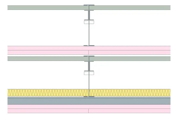
Horizontal upper framework comprising of Gypframe 146 TI 90 Tabbed ‘I’ Studs at 600mm centres with Gyproc CoreBoard 19mm between studs, secured by Gypframe G102 Retaining Channel. Two layers of Gyproc FireLine 15mm to ceiling side. Lower framework comprising of Gypframe 146 TI 90 Tabbed ‘I’ Studs at 600mm centres with Gyproc CoreBoard 19mm between studs, secured by Gypframe G102 Retaining Channel. Gypframe MF5 Ceiling Sections fixed perpendicular to Gypframe 'I' Studs on ceiling side at 450mm centres. Two layers of Gyproc FireLine 15mm to ceiling side and 25mm Isover Acoustic Partition Roll (APR 1200) in the cavity.
Read more
Read less
Fire Integrity (mins)
120
Fire Insulation (mins)
120
Sound Insulation (Airborne) Rw (dB)
50
System Depth (mm)
404
Maximum Span (mm)
4400
Standards
| Standards | Standard types |
|---|---|
| StandardsBS EN 1364-2,Fire resistance tests for non-loadbearing elements - Ceilings. | Standard types |
| StandardsBS 2750-3,Measurement of sound insulation in buildings and of building elements. Laboratory measurements of airborne sound insulation of building elements. | Standard types |
Products
Details
This section should be read in conjunction with the Products list.
- Abutment Fixing: Channels suitably fixed to abutment at 600mm centres in two lines staggered by 300mm.
- Framework Fixing: Gypframe 'I' studs fixed in to Gypframe channel through bottom flange with two wafer head screws.
- Finishing Requirements: To achieve the specified performances, the system should be finished using either one of our Thistle or ThistlePro plasters, or Gyproc jointing products. See the product range guides on the British Gypsum website for more information.
- Horizontal Joint: Horizontal board joints in core layer closed off by inserting steel angle between board joints and 122mm strip of core board fire stop with beads of sealant along both longer edges fixed to angle using three drywall screws.
- Loadbearing: No
- Maximum Span (mm): 4400 mm
- Other Requirements: SpecSure® system performance warranty confirms that British Gypsum proprietary systems will perform as specified for the lifetime of the building. The SpecSure® warranty requires that all components are specified in full and constructed in accordance with British Gypsum’s installation guidance. For more details see the British Gypsum website. Always check with the design team before making any changes to the chosen specification, ensuring appropriate substantiation is sought to confirm that the solution still meets all required project performances.
- Perimeter Framing: Perimeter channel positioned tight up to abutment channels and suitably fixed to background at 600mm centres.
- Retaining Channel: Retaining channels inserted between the face of the coreboard and the lower flange of the stud / starter channel.
- Screw: Fix all ceiling boards securely to all supports at 230mm maximum centres in the field of the board and at 150mm maximum centres along the short board ends and at ceiling perimeters. All joints staggered between layers. Fix working from the centre of each board. Position screws not less than 13mm from cut edges and 10mm from bound edges of boards. Set screw heads flush with plasterboard surface; do not break paper or gypsum core.
- Sealant: Locate sealant at junctions with adjoining structure and other air paths. Apply as a continuous bead to clean, dry, dust-free surfaces, leaving no gaps. For pressurised airshafts and service ducts apply a continuous bead of sealant leaving no gaps to all framing members at perimeter junctions with walls, air gaps around openings, and other potential air leakage points. To frame members prior to fitting core boards and around fire stops cloaking horizontal core board joints. To all metal framing around board perimeters of first layer boarding and board perimeters when fixing outer layer board.
- Approx. Weight (kg/m2): 88 kg/m²
- Secondary Framework Centres (mm): 450 mm
- Lower Framework Stud Centres (mm): 600 mm
- Secondary Framework: Secondary framework fixed to primary framework using two wafer head screws per connection.
- Upper Framework Stud Centres (mm): 600 mm
Documents
Need CAD, BIM, Test Reports and Technical Specifications?
Log in to access CAD .dwg files.
Log in and add a System Specification to a Project to access BIM files, Test Reports, and Technical Specification files.
Test Reports
Please add this Specification to a project and go to that Project to access the related Test Reports.
| Test report label | Test report name |
|---|---|
| Test report labelFire Resistance Test Report | Test report nameBTC 20980F |
| Test report labelSound Insulation Test Report | Test report nameBTC 190LC |
Image


SpecSure
A unique warranty that confirms British Gypsum proprietary systems will perform as specified for the lifetime of the building.