GIWL 92 I 90 PIR (B) (EN)
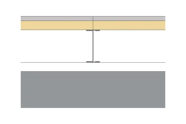
One layer of Gyproc ThermaLine PIR 38mm to one side of Gypframe 92 I 90 ‘I’ Stud framework forming an independent lining to masonry background. For heights up to 5100mm.
Read more
Read less
Maximum Height (mm)
5100
GIWL 92 I 90 PIR (B) (EN)
Products
| Fixing strap | Gypframe GFS1 Fixing Strap |
| Fixing T | Gypframe GFT1 Fixing 'T' |
| Stud | Gypframe 92 I 90 'I' Stud |
| Sealant | Gyproc Sealant |
| Thermal sealant | Gyproc Sealant |
| Board side 1 | Layer 1: Gyproc ThermaLine PIR 38mm |
| Abutments and openings | Gypframe 92 S 50 'C' Stud |
| Base channel | Gypframe 94 DC 60 Deep Flange Floor & Ceiling Channel |
| Head channel | Gypframe 94 DC 60 Deep Flange Floor & Ceiling Channel |
| Screws side 1 | Layer 1: British Gypsum Jack-Point Screws 60mm |
Details
This section should be read in conjunction with the Products list.
- Abutment Fixing: Gypframe 'C' stud suitably fixed to structure at 600mm centres in two lines staggered by 300mm.
- Background: Masonry
- Base Channel Fixing: Gypframe channel suitably fixed to floor at 600mm centres in two lines staggered by 300mm.
- Deflection Allowance: Vertical deflection only. To be determined by a Structural Engineer.
- Dropped Soffit: For principles of deflection head construction refer to detail ST‐224-Z2LA-06
- Finishing Requirements: The system should be finished using either one of our Thistle or ThistlePro plasters, or Gyproc jointing products. See the product range guides on the British Gypsum website for more information.
- Fixing Strap: Used to support horizontal board joints and enable board screw fixing at 300mm centres.
- Fixing T: Used to support horizontal board joints and enable board screw fixing at 300mm centres.
- Loadbearing: No
- Maximum Height: The maximum heights quoted are based upon a limiting deflection of L/240 at 200 Pa.
- Other Requirements: SpecSure® system performance warranty confirms that British Gypsum proprietary systems will perform as specified for the lifetime of the building. The SpecSure® warranty requires that all components are specified in full and constructed in accordance with British Gypsum’s installation guidance. For more details see the British Gypsum website. Always check with the design team before making any changes to the chosen specification, ensuring appropriate substantiation is sought to confirm that the solution still meets all required project performances.
- Screw: Board layer 1, fix securely to Gypframe metal supports around the perimeter of the board and intermediate stud positions at maximum 300mm centres. External corners reduce fixings to 200mm. Drywall screws can be used for fixing boards to metal profiles with a thickness of 0.8mm or less (excluding 'I' studs). Fix working from the centre of each board. Position screws not less than 13mm from cut edges and 10mm from bound edges of boards. Set screw heads flush with plasterboard surface; do not break paper or gypsum core.
- Sealant: Locate sealant at junctions with adjoining structure and other air paths. Apply as a continuous bead to clean, dry, dust-free surfaces, leaving no gaps. After application of sealant, bulk fill gaps between floor and underside of plasterboard using Gyproc jointing compound.
- Stud Centres (mm): 600 mm
- Head Channel Fixing: Gypframe channel suitably fixed to soffit at 600mm centres in two lines staggered by 300mm.
- Minimum Cavity / Offset (mm): 30 mm
- Framework / Lining: One Side
Documents
Need CAD, BIM, Test Reports and Technical Specifications?
Log in to access CAD .dwg files.
Log in and add a System Specification to a Project to access BIM files, Test Reports, and Technical Specification files.
Image


SpecSure
A unique warranty that confirms British Gypsum proprietary systems will perform as specified for the lifetime of the building.