D150001 (C) (EN)
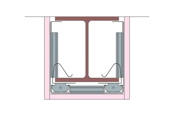
One layer of Gyproc FireLine 15mm providing 60 minutes fire protection to steel columns or beams up to a section factor A/V (HP/A) m-1 (max) of 183 at a critical temperature of 550oC.
Read more
Read less
Fire Protection (mins)
60
Framed / Frameless
Framed
Maximum Section Factor (m-1)
183
Standards
| Standards | Standard types |
|---|---|
| StandardsBS EN 13381-4,Test methods for determining the contribution to the fire resistance of structural members: Applied protection to steel members. | Standard types |
Products
| Fixing T | Gypframe GFT1 Fixing 'T' |
| Perimeter framing | Gypframe GA2 Steel Angle |
| Stud | Gypframe GL1 Lining Channel |
| Encasement board screws (board to metal) | Layer 1: British Gypsum Drywall Screws 25mm |
| Clips | Gypframe GL10 GypLyner Steel Framing Clips |
| Channel connector | Gypframe GL3 Channel Connector |
| Encasement board | Layer 1: Gyproc FireLine 15mm |
| Framework fixing | British Gypsum Wafer Head Drywall Screws 13mm |
Details
This section should be read in conjunction with the Products list.
- Background: Steel column or beam
- Finishing Requirements: To achieve the specified performances, the system should be finished using either one of our Thistle or ThistlePro plasters, or Gyproc jointing products. See the product range guides on the British Gypsum website for more information.
- Installation: Fix continuous lengths of steel angle onto face of innermost steel flanges or background using suitable fire resistant fixings at 600mm centres (3-sided encasement only). Friction fit framing clips to steel flanges at 800mm maximum centres and 100mm from each end of encasement; ensure that clips are fully engaged and aligned. Lining channels are clipped over steel framing clips and can be extended by using channel connectors. For single layer encasements joints, install Gypframe GFT1 Fixing 'T' or short sections of lining channel with ends tabbed and fixed to framing using wafer head screws. For multiple layer encasements, Install fixing strap between layers to support outer layer board joints. Stagger joints between adjacent faces and between layers by a minimum 600mm centres. If the steel section web or flange dimension exceeds 600mm, a nogging should be formed from lining channels with ends tabbed, installed at 600mm maximum centres, fixed to framing using wafer head screws. Fix noggings to coincide with a board end joints.
- Loadbearing: No
- Other Requirements: SpecSure® system performance warranty confirms that British Gypsum proprietary systems will perform as specified for the lifetime of the building. The SpecSure® warranty requires that all components are specified in full and constructed in accordance with British Gypsum’s installation guidance. For more details see the British Gypsum website. Always check with the design team before making any changes to the chosen specification, ensuring appropriate substantiation is sought to confirm that the solution still meets all required project performances.
- Screw: Boards are fixed securely to Gypframe metal supports at maximum 300mm centres. Fix working from the centre of each board and position screws not less than 13mm from cut edges; 10mm from bound edges of boards. Set screw heads flush with plasterboard surface; do not break paper or gypsum core.
- Encasement: The maximum permitted steel size which can be encased is 600mm.
Documents
Need CAD, BIM, Test Reports and Technical Specifications?
Log in to access CAD .dwg files.
Log in and add a System Specification to a Project to access BIM files, Test Reports, and Technical Specification files.
Test Reports
Please add this Specification to a project and go to that Project to access the related Test Reports.
| Test report label | Test report name |
|---|---|
| Test report labelFire Resistance Test Report | Test report nameBTC 21648FA |
Image


SpecSure
A unique warranty that confirms British Gypsum proprietary systems will perform as specified for the lifetime of the building.